With so many opportunities emerging in fiber optics, engineers are increasingly looking to make the transition to fiber in their new designs. However, it’s not as easy as just picking a fiber cable. What does it really take to implement an optical interconnect? Let’s look at the key elements required for fiber optics from end-to-end so that you can more confidently design fiber into your next project and take advantage of all that fiber has to offer.
There are three primary functional blocks needed to implement an optical link: (1) conversion of the electrical signal to light for transmission, (2) an optical transmission media, and (3) conversion of the received optical signal back to electrical.

Components needed for a fiber optic subsystem
The Transmitter Optical Subassembly (TOSA)
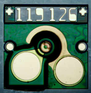
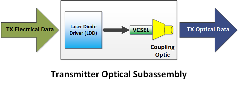
The TOSA converts the electrical signals to optical signals, essentially just converting the ‘1’s and ‘0’s from electrical to optical data. The laser diode driver (LDD) is the integrated circuit that receives the electrical signal and converts it to an output suitable to drive the laser. The laser is operated at a specific drive current, then the LDD slightly increases the drive current for a ‘1’ and slightly decreases it for a ‘0’. This is also referred to as the optical modulation amplitude. A vertical-cavity surface-emitting laser, or VCSEL, is typically used as the light source in a fiber optic interconnect because the light output pattern is circular and easily couples into the circular core of an optical fiber. Other light sources used include edge-emitting semiconductor lasers – which have an elliptical output shape, and even light emitting diodes (LEDs) – which have a broader emission spectrum and are therefore only suitable for low bandwidth and very short distances like optical S/PDIF audio.

The final element of the TOSA is the optical coupling of the laser output into an optical fiber. The light output from the laser needs a lens to couple the light into the core of the fiber, which is typically only 50μm for a multimode fiber, making this a critical part of the transmission process. A lens block with an integrated fiber coupling mechanism is typically used so that the fiber can simply plug into the unit in the field. However, because the coupling is so critical and must be maintained over the entire operating temperature range, all elements in the design need to be carefully modeled and fully tested to ensure that good optical coupling is maintained in all operating conditions.

The transmitter assembly converts the electrical signal to an optical signal.
Optical Fibers
The optical signal is transmitted along an optical fiber from the transmitter to the receiver. The fiber used must match the type of optical output of the laser(s) in the transmitter, as not all fibers are equal. There are single-mode fibers and multimode fibers, which refers to how the light is output from the lasers. A single-mode laser should use single-mode fiber and a multimode laser should use multimode fiber. In general, multimode fiber is used for shorter distances and single-mode is used for longer distances. For example most multimode devices support distances of up to 300m over multimode fiber, Inneos Real 4K optical subsystems support up to 1000 m over multimode fiber, whereas the optical fiber that may run underground to your home (FTTH) is single-mode because the optical signal needs to be transmitted from many kilometers away at your ISP’s fiber hub.
Another thing to consider when choosing fiber is the configuration of the fiber cable. If the light output is from just one laser OR if the output of multiple channels is combined into a single column of light during the optical coupling in the transmission block (like the Inneos Wavestacker), then you only need one fiber for the transmitter. If the optical output is from multiple channels that are each run on a separate fiber, then you will need a fiber for each channel (parallel fiber). An optical interconnect is also often configured as a transceiver, so there are both transmitter and receiver blocks on both ends of the link. If both ends use the same wavelength channels, then you need a separate fiber for the return channel.
Optical interconnects also offer some exciting possibilities compared to copper because fiber can simultaneously transmit and receive multiple channels as long as the wavelengths are different. In the same way that, if you hold a prism up to a sunbeam and it splits up the constituent colors (wavelengths), so too can this be done with different data channels. This means that optical interconnects can maximize bandwidth utilization and minimize weight by adding multiple wavelength channels on the same fiber, as the Inneos optical subsystems do, and you only need one fiber for bi-directional data.

An optical lens can be used to multiplex optical channels of different wavelengths for simultaneous transmission.
Connectors are another important element of the fiber transmission media because the connection needs to be simple yet robust, and suitable for the environment. Typical connectors are LC, SC, ST, FC, MTP. It is important to make sure that the fiber cable has the same connector as the optical coupling element of the transmitter or receiver optic.
The Receiver Optical Subassembly (ROSA)
The final element of the fiber optic interconnect is the receiver block, which implements the reverse process of the transmitter block. The key elements of the receiver include a lens, a photodetector, a transimpedance amplifier (TIA) and a limiting amplifier (LA). The coupling optic focuses the light from the fiber onto the PIN photodetector. The photodetector converts the received light to electrical current, with the electrical signal being proportional to the received light intensity. This small electrical signal is then sent to the TIA integrated circuit, where it is converted into a balanced signal with a larger amplitude, and then to a limiting amplifier circuit to generate an output electrical signal. Ideally, this signal is identical to the input electrical signal way back at the input to the transmitter LDD.

Functional block diagram of the receiver that converts the signal from optical back to electrical.
Using Fiber Optics in the Real World
It is important to remember that these functional elements also need to be assembled into a mechanical form factor that is suitable for the environment into which the fiber interconnect subsystem will be installed. For example, in a data center environment, an SFP+ or QSFP+ form factor has a card edge electrical connector, LC or SC optical connector, and typically operates from 0°C to 70°C. This is vastly different from the operating environment that a transceiver installed on a military aircraft would experience, where connectors need to be much more rugged and vibration-tolerant. Inneos has experience developing fiber optic interconnects for a wide range of operating environments and applications, so we can help you choose the right components for your system design when you’re ready to take your connectivity to the next level.
